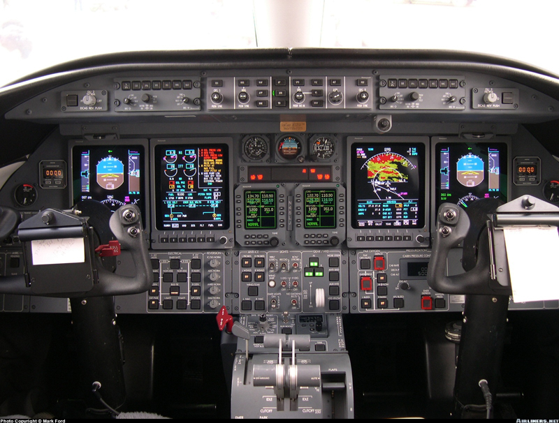
Click on a component of the LEAR 45 cockpit to find out what it does.
|
|
Pilot's and Copilot's Display Controller
The display controllers, located on the glare-shield, provide immediate access to and control of the objects on the PFDs. Each controller is configured with seven push buttons located on the front panel along with two rotary knobs used for reference selection for bearing source, two concentric knobs for DU dimming and a momentary push button (located inside concentric DU knob) used to initiate a system test. The display controllers also provide a data acquisition function, collecting inputs from sources such as the bezel controllers, guidance controller, joystick, etc. The controllers pass these inputs to the corresponding IC-600 for processing.

The display controller buttons are as follows:
1. IN/HPA — Inches of mercury or hectopascals.
2. CUE — Selection of single cue or cross pointer command bars.
3. FPA — Controls selection and deselection of the flight path angle symbol and flight path acceleration display.
4. WX — Select or deselect weather radar display on the PFD.
5. HSI — Provides up to three different display options on the HSI.
6. FMS — Allows a navigation display of FMS information (alternately FMS 1 or FMS 2 if dual) to be selected for display on the PFD.
7. NAV — Alternately selects NAV 1 or NAV 2 as the source of NAV data on the HSI.
FLIGHT GUIDANCE CONTROLLER (FGC)
The Flight Guidance Controller (Figure 5-18) is the prime controller for the flight director and the autopilot/yaw damper. Located on the center glareshield, the FGC provides the means, via push button switches, for flight director mode selection, couple status and autopilot/yaw damper engage selection. Flight director modes engage status is indicated to the crew via a green light on the right edge of each mode switch, which is illuminated when the mode is active and extinguished when the mode is inactive or dropped. The controller also has several rotary controls enabling selection of IAS, MACH, and VS targets, altitude, course and heading. All push button selections are signaled to both IC-600s via a discrete output from the FGC. The IC-600s then provide the drive to illuminate the appropriate light on the FGC.

The FGC annunciations and controls are as follows;
FD 1/2 buttons — The flight director buttons (FD 1 and FD 2) are located on the upper left/right corners of the flight guidance controller. Depressing these buttons alone will not bring the FD command bars into view. Any FD mode selection causes the FD command bars to appear on both PFDs. When the FD command bars are in view on both PFDs and the autopilot is not engaged, depressing the master side FD button will disengage all FD modes and remove the command bars from both sides. Pressing the slave side FD button will remove the command bars from the PFD on that side acting as a flight director clear function.With the autopilot engaged, the FD command bars will be in view at all times on the coupled side and cannot be removed from the PFD. The opposite side FD command bars can be removed from view by depressing the appropriate FD 1 or FD 2 button.
Course set knobs — A course set knob (CRS 1 and CRS 2) is located at each end of the FGC. These knobs are used to individually set the courses on the left and right PFD HSI displays. They are used primarily to set the course for a VOR radial or LOC course. The course knobs have a push button in the center to synchronize the display to the aircraft’s “direct-to” course.
Heading set knobs — Heading is selected via a rotary knob, with a “Heading Bug” symbol on the face of the knob. The heading knob controls the heading bug and digital display on both PFDs and the bug on the MFD MAP display. Depressing the HDG knob will synchronize the HDG bug on all display units to the aircraft’s current heading.
HDG (heading) button — Depressing the HDG button engages the heading mode and displays a green HDG annunciation on the PFDs. The flight director command bars will command a turn in the direction the heading bug was moved to achieve the set heading. Heading select is used to maintain a magnetic heading. The heading bug is positioned to the desired heading on the HSI using the HDG knob on the FGC. The heading select mode is canceled when any armed lateral mode captures or if GA is selected.
NAV (navigation) button — Pressing the NAV button alternately selects and deselects the navigation mode. The NAV mode is normally used to intercept route segments identified with VOR radials and to intercept and fly desired FMS tracks (SIDs, routes, holding and STARS).
APP (approach) button — The intended function of the APP mode is that APP be used for all approaches, regardless of nav source or whether a vertical mode is also associated with the approach. The APP mode is normally used to select lateral and vertical steering for ILS and FMS. The VOR approach mode is selected by pressing the APP mode button with the navigation receiver tuned to a VOR frequency and selected as the active nav source. Pressing the APP button arms both localizer and glideslope modes when the navigation receiver is tuned to an ILS frequency and ILS is selected as the active navigation source. Selection of
APP mode when the nav source is FMS engages the FMS lateral mode the same as described for NAV and also arms VNAV for approach.
BNK (bank) button — Pressing this button alternately selects or deselects a reduced maximum bank angle of 14° (for all lateral modes, except roll) on both FDs. When selected, a green low bank arc appears on the top of the ADIs and BNK is annunciated on the PFD.
AP (autopilot) button — Depressing this button engages the autopilot. Depressing a second time disengages the autopilot.
XFR (transfer) button — Located in the center section of the FGC. The XFR button is used to select the desired flight director (left or right) to command the autopilot.
YD (yaw damper) button — Depressing this button engages yaw damper. The YD can be engaged independent of the AP, but the autopilot system will not engage, or remain engaged, without the YD.
SPD (speed) knob — The rotary SPD knob is used to change the IAS/ Mach speed reference (SPD mode) and the vertical speed reference (VS mode). The speed knob changes the bug airspeed at any time, as long as VS is not selected. When VS mode is engaged, rotation of the SPD knob changes the digital vertical speed reference and the vertical speed bug position. The integral PUSH IAS/M button within the SPD knob is used to toggle the airspeed tape between IAS and Mach. The master flight director computes the airspeed reference, and the slave flight director synchronizes to this reference.
SPD (speed) button — Depressing the SPD button engages the speed hold mode (IAS or Mach) on both FDs. The speed select mode is used to fly to a selected airspeed or Mach number, and to provide limited overspeed/underspeed protection during climbs and descents. When speed select mode is active, a green IAS or Mach annunciation is displayed in the captured vertical mode field on the PFDs.
FLC (Flight Level Change) button — Depressing the FLC button once engages the normal climb/descent profile on both PFDs. Depressing it a second time selects the high speed climb/descent schedule. A third depression deselects the mode. The FD chooses between the climb and descent schedule based upon the aircraft’s present altitude and preselected target altitude. The FD annunciation on the PFD is FLC for the normal profile and FLCH for the high speed profile. VS (Vertical Speed) button — Depressing the VS button engages the vertical speed hold mode on both FDs. When VS is selected, the speed bug disappears and reference goes to dashes.The FD commands pitch changes to hold the vertical speed that existed at the time of engagement. Once engaged, the vertical speed bug positions on the inner side of the vertical speed scale and a digital readout appears above the vertical speed indicator.
VNV (Vertical Navigation) button — Depressing the VNV button arms, then captures the FMS pitch steering commands of the FDs if FMS is selected as the NAV source, the FMS is programmed for a vertical navigation profile, the altitude preselector is set below existing altitude and the aircraft is within the TOD (top of descent) window. When the VNAV mode is armed, a white VNAV is annunciated on the PFDs in the FD vertical mode annunciation field and will turn green upon
capture
ASEL (Altitude Select) knob — The preselected altitude is set via the ASEL rotary knob on the FGC. The altitude preselect mode provides a means for FD/AP to climb or descend to a preselected altitude and then level off and maintain the preselected altitude. The ASEL knob is used to set the altitude preselect function, and also provides the altitude reference for the altitude alerter function. ALT (Altitude Hold) button — Altitude hold may be engaged by depressing the ALT button on the FGC. When ALT is engaged, the FD commands pitch to hold the existing altitude at the time the ALT button was depressed, or at the ASEL reference altitude if ALT automatically engages.
DISPLAY UNIT REVERSION PANELS
A display unit reversion panel is located on the glareshield above the PFDs on each side of the cockpit. The panel on the pilot’s side is for controlling the display on DU #2 and the panel on the copilot’s side is for controlling the display on DU #3. The reversion selector knob on these panels plus the push function of the knobs allow the operators to switch the inboard DUs (DU #2 and DU #3) to display either PFD, MFD, or EICAS formats. With both reversion selector switches in NORM, an EICAS format is displayed on DU #2 and an MFD format on DU #3. Depressing the selector knob on either reversion panel flip-flops the DU #2 and DU #3 displays, reversing the MFD and EICAS display locations. Placing the reversion selector to the PFD position on either side causes the PFD format to move to the inboard display tube on that side and the outboard display to blank.
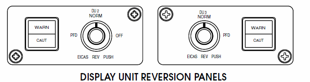
It is important to note that when selecting display unit reversion, the bezel controllers on DU #1 and DU #4 continue to work with the PFD display when it is transferred to an inboard display unit. The airplane master warning/caution lights are also located on the display unit reversion panels.
A solid state Cockpit Voice Recorder (CVR) is installed in the Learjet 45. The standard CVR is a three-channel unit providing 30 minutes of recording. An optional unit is available which provides 120 minutes of recording. Two of the channels are used to record pilot and copilot audio. The third channel is used for the area microphone. Located in the tailcone, the CVR is painted international orange with reflective tape added to aid in recovery following a mishap. It also has an underwater locator beacon installed on one end of the unit. The recording is converted to a digital format and stored in crash protected memory. The area microphone is located in the upper center area of the instrument panel. An erase button and headphone jack are located on the CVR panel just beneath the copilot audio control panel. The CVR performs a self-test at power-up and has a continuous self monitor. If a fault is detected at any time, an annunciation is posted on CAS.
STANDBY AIRSPEED/MACH INDICATOR
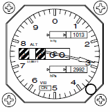
The standby altimeter displays baro corrected altitude in a pointer/ counter drum display. The dial graduations are marked every 20 feet. Above sea level the counter displays every 100 feet up to 55,000 feet of operational range. The indicator has dual barometric correction, from 27.9 to 31 inches of mercury and 946 to 1050 hectoPascals. Back lighting is provided by 5-vdc to illuminate the standby altimeter indicator at night.
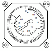
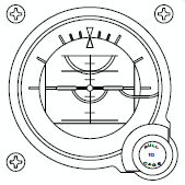
STANDBY ATTITUDE INDICATOR
The standby attitude indicator provides a visual indication of the airplane flight attitude. It is located in the center of the standby instrument group where it can be viewed easily by both pilots. It is powered from the emergency battery bus so that it will remain powered for at least one hour after the loss of airplane generator power. The standby attitude indicator will continue to provide an accurate display of aircraft attitude for a further nine minutes after the loss of all airplane power. The indicator is an electrically-driven gyro whose vertical attitude is maintained by a mechanical erection system. The power warning flag is pulled from view after the gyro has spun up to valid operating speed and reappears if there is any interruption of source power or the unit is
in caged mode. Back lighting is provided by 5-vdc to illuminate the standby attitude indicator at night.
The standby altimeter displays baro corrected altitude in a pointer/ counter drum display. The dial graduations are marked every 20 feet. Above sea level the counter displays every 100 feet up to 55,000 feet of operational range. The indicator has dual barometric correction, from 27.9 to 31 inches of mercury and 946 to 1050 hectoPascals. Back lighting is provided by 5-vdc to illuminate the standby altimeter indicator at night.